SIM800C-Module
⚡ SIM800C-Module ⚡
If you like SIM800C-Module - give it a star, or fork it and contribute!
This repository contains the open-source schematic and PCB design files for a SIM800C-Module development board clone, created using Altium Designer. This board allows you to work with the Sim800C microcontroller using the Digispark platform.
Support My Work and Future Projects: 🚀✨
If you’d like to contribute and help bring more exciting projects to life, consider sponsoring my work. Every bit of support is greatly appreciated and helps me continue creating valuable tools and solutions.
🟠 As a freelancer, you can also find me on:
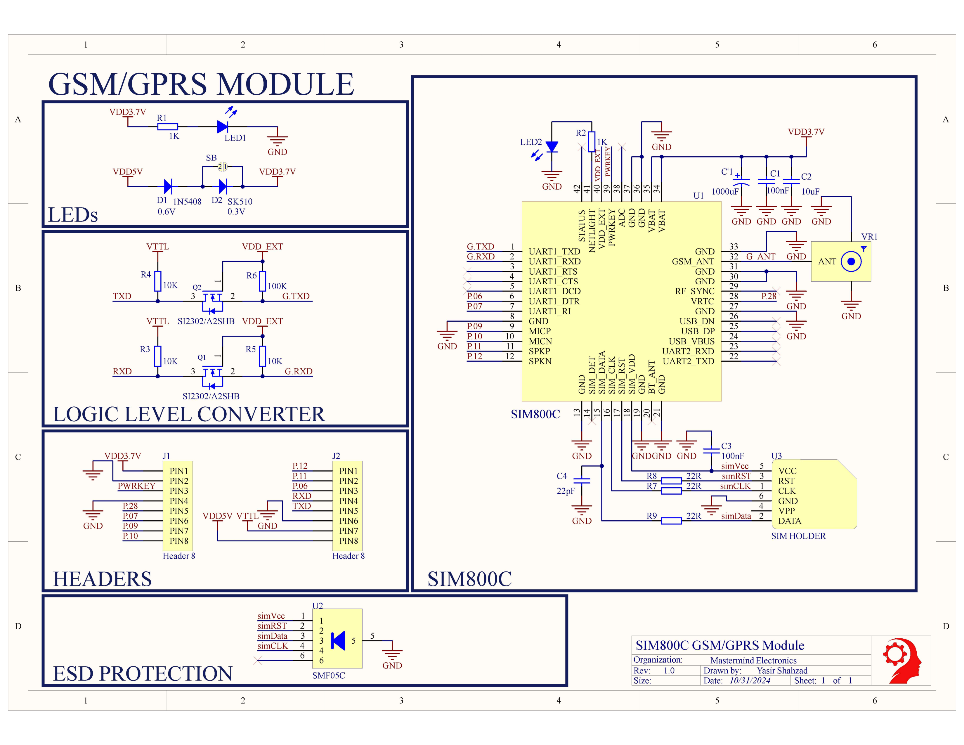
Schematic Diagram 📉
The complete schematic diagram shows the electrical connections and components used in the design.

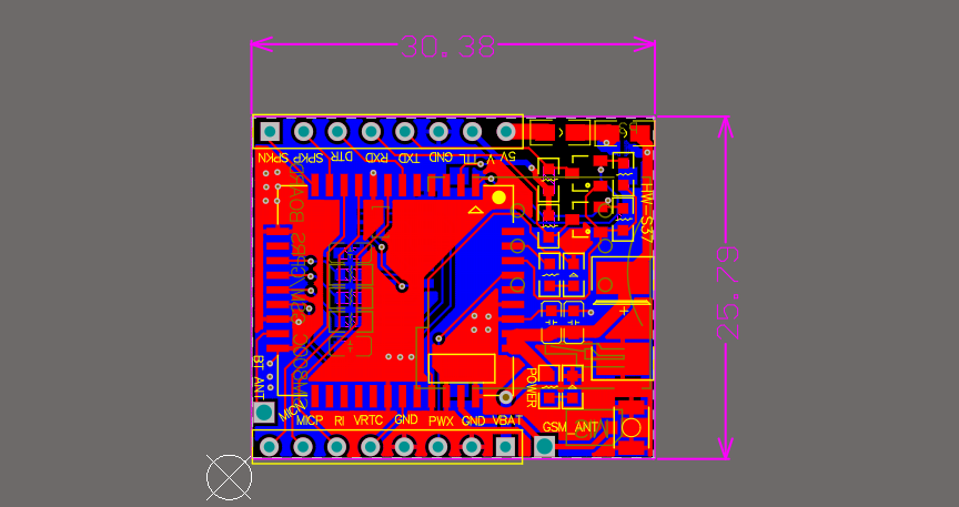
PCB Layout 🖼️
The PCB layout represents the physical arrangement of components on the printed circuit board, detailing how they are positioned and connected.

Features 🌟
- Power Supply via USB or External 5V 🔌 for flexible power options.
- Quad-Band GSM/GPRS Module 📶 supporting 850/900/1800/1900 MHz bands for global connectivity.
- AT Command Interface 💻 for easy communication with microcontrollers and computers.
- TCP/IP, HTTP, FTP Protocols 🌐 for versatile data communication over the internet.
- SMS and Voice Call Support 📞 for messaging and voice applications.
- Onboard 5V to 3.3V Regulator 🔋 ensuring stable power for the module.
- Antenna Connector 📡 I-PEX antenna connector for extended network range.
- Power Saving Mode ⚡ to reduce power consumption during idle periods.
- Status Indicators 💡 for network and power statuses.
- Compact Form Factor 📏 ideal for embedded and IoT projects.
Requirements 📋
- 🛠️ Altium Designer (or a compatible viewer)
Images 📸

🔼 Top 3D View |

🔽 Bottom 3D View |

🔼 Top Layout |

🔽 Bottom Layout |
|---|
Getting Started 🚀
- Download the repository: 🟢 Click “Clone or download” on the green button above.
- Open the project: 🖥️ Use Altium Designer to open the
.PrjPCBfile located in the main directory. - Schematics: 📜 The
schematic.SchDocfile shows the electrical connections and components used in the design. - PCB layout: 🧩 The
PCB.PCBDocfile represents the physical layout of the components on the printed circuit board. - Generate BOM (optional): 🛒 Use Altium Designer’s BOM generation features to create a list of required components.
Additional Information ℹ️
- Firmware: This repository does not include firmware. A separate repository is available with HTTPS, MQTT, and additional features. You can find it here:SIM800C Firmware
- Assembly instructions (optional): 🔧 Consider adding a separate document or webpage with detailed instructions on soldering and assembling the PCB (if applicable).
- License: 📄 Specify the open-source license used for the design files (e.g., MIT License).
Contributing 🤝
We encourage contributions to this project! Feel free to submit pull requests with improvements, bug fixes, or additional features.


